AutoDXFPro
The desktop predecessor to AutoDXF2D — a rule-driven mapping engine that turns unstructured CSV exports into clean, correctly-shaped DXF files for CAD and nesting software.

The problem
Part data arrives as CSV exports where the shape of a part is buried in a text string. A tag like SP0201250304004000120375 encodes material, thickness, and part number, and somewhere in the naming convention is the fact that it's a plate with a rounded corner. A human reads that and draws it. A machine needs it written down explicitly.
AutoDXFPro was built to make that translation rule-driven instead of manual.
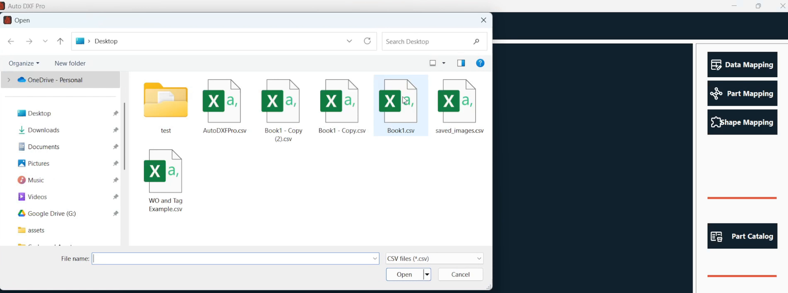
The mapping model
Everything hangs off a three-level hierarchy that mirrors how the shop actually thinks about parts:
| Level | What it means |
|---|---|
| Tag → Part type | Group the raw tags from the CSV into meaningful part categories. A new tag appears? Create a part type and assign it. |
| Part type → Shape | Decide what geometry a part type is drawn as. Assign multiple shape types to one part type where the data calls for it. |
| Shape → Geometry | The base-shape handlers turn dimensions into actual contours. |
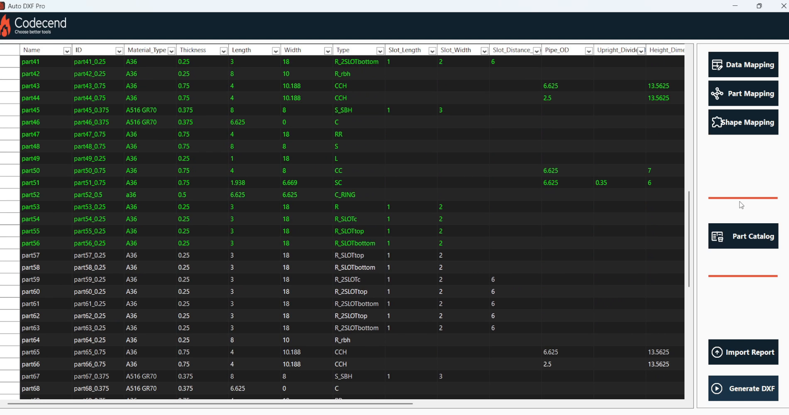
Shape library
Shipped with dedicated handlers rather than one monolithic drawing routine:
- Circles
- Rectangles
- Rounded rectangles
- L-shapes
- Center cope — a cope applied to the center of a member
- Split cope — a cope split across a member
- Center cope height — cope geometry with an explicit height parameter
- Etched cope — cope geometry with an etched region
The cope handling matters: cope cuts are where pipe junctions meet plate, and getting them wrong means a part that doesn't fit. Giving each cope variant its own handler kept that logic testable and separate.
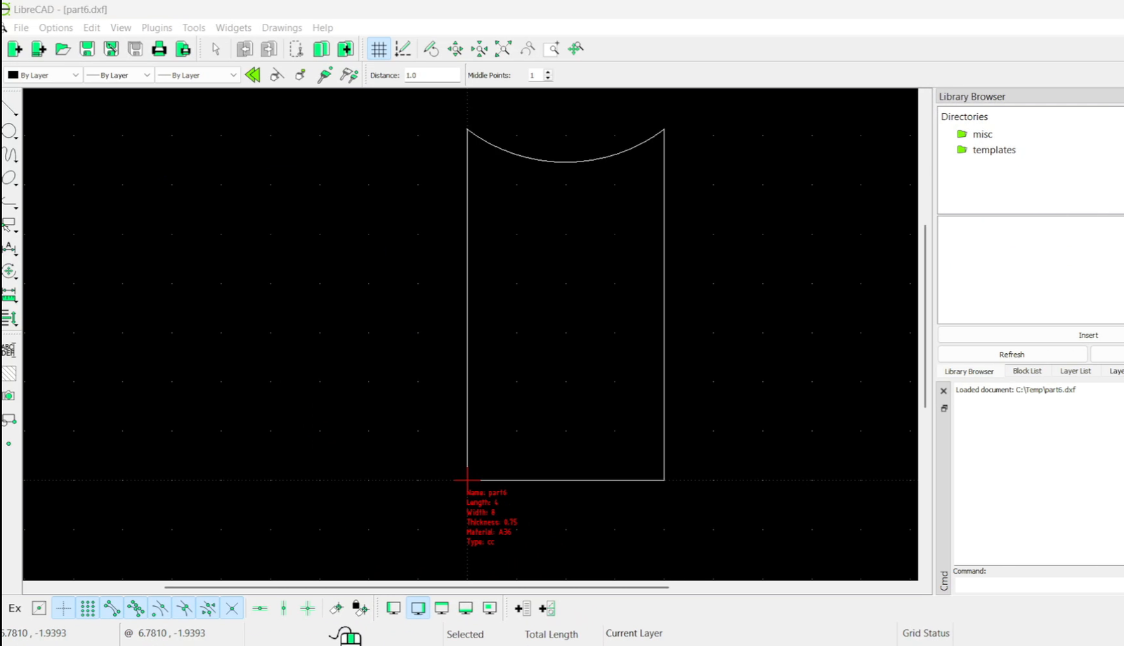
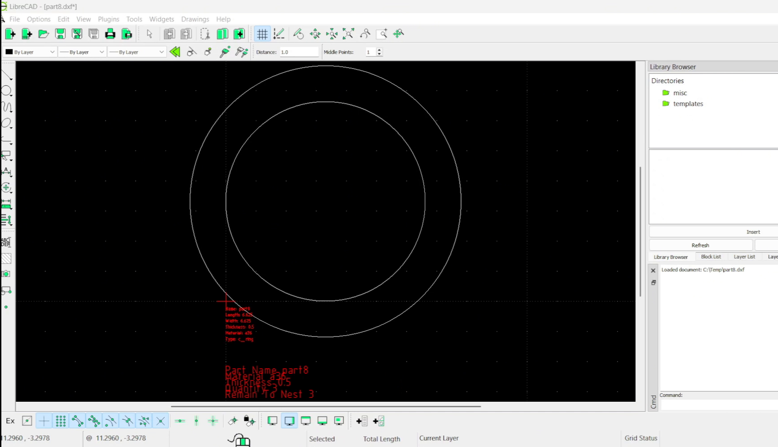
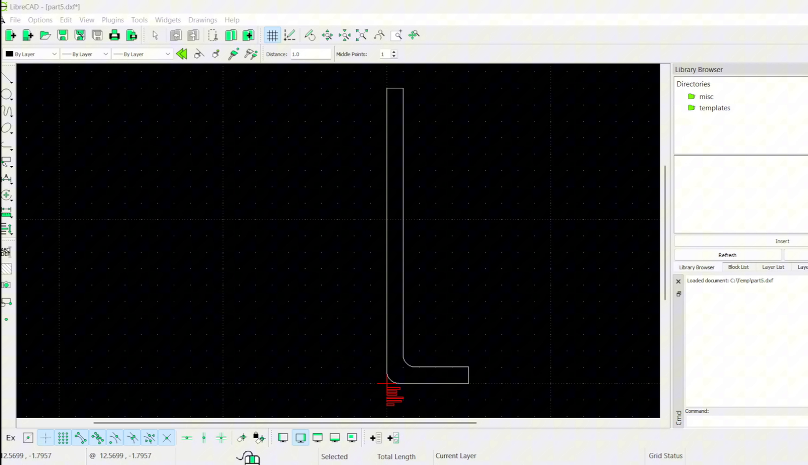
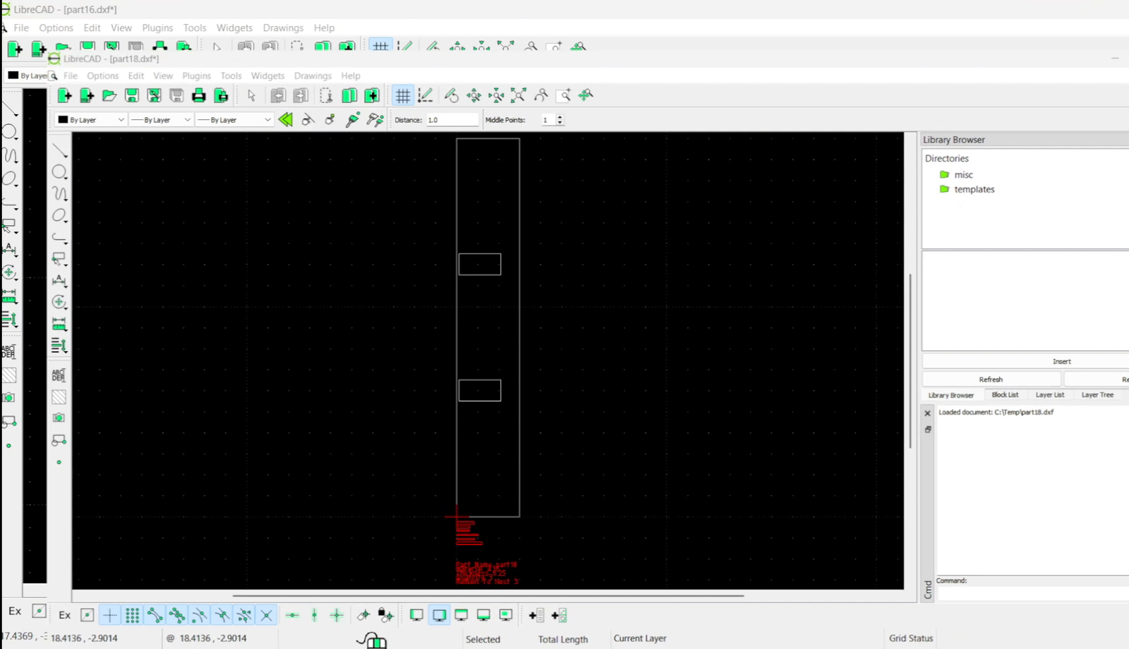
The rules engine
Mapping a CSV cell to a dimension means parsing text. AutoDXFPro lets you write that parsing as rules rather than code:
- String functions — LEFT, MID, RIGHT for positional extraction.
- Delimiter logic — split on -, _, spaces, or anything else present in the export.
- Combine or split cells, or deliberately ignore them.
- Saveable rule sets — build the rules once for a data source and reuse them for every future import.
Every customer and every upstream system exports part data a little differently. If changing an extraction meant recompiling, the tool would be dead within a month. Making the rules user-editable is what let it survive contact with real data.
Handling messy data
Real exports are incomplete. AutoDXFPro doesn't silently drop a bad row — it flags it:
- Notifies you when data is incomplete and offers per-row choices: override it, skip it, or swap it.
- Collects every flagged entry into a final DataGrid for bulk editing.
- Supports typing and copy/paste in that grid, so a batch of fixes takes seconds.
PDF-assisted verification
Two modes let the drawing help you check the data:
- Reference mode — put the PDF beside the CSV rows and match them visually.
- Text extraction mode — pull text out of the PDF to assist shape mapping and validation.
Export naming
Output filenames are built from your own string logic, so files land in the downstream system already named correctly. A template like WorkOrder_Material_Thickness_PartNumber can pull dynamic values — RIGHT(ID, 1) and friends — and output paths are configurable per project or batch.
Generating the batch
Once the mapping is set, generation is a single pass over the whole import. Every part is written out as its own DXF, named by the export template, and the run reports how long it took so you know what you're waiting on before you start.
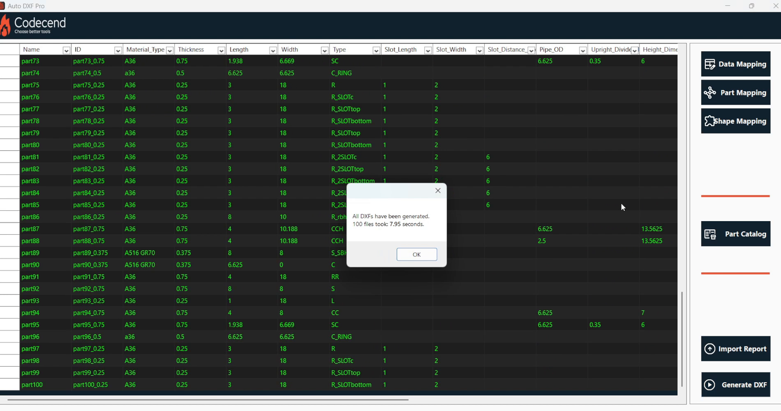
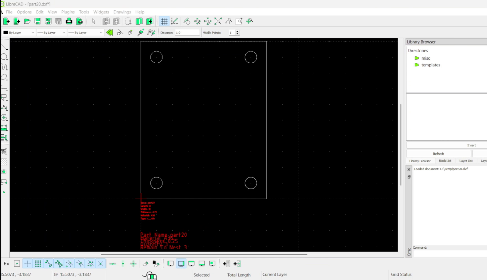
Why a web successor
AutoDXFPro proved the concept: shops will trust generated geometry if it's verifiable. What it couldn't do was be shared and supervised. It was a desktop app, so every update meant touching every machine, and there was no way to enforce who could generate what or how many parts they were producing.
AutoDXF2D takes the same core idea — map CSV, assign shapes, generate verified CAD — and rebuilds it as a private-team web platform with revisioned drafts, per-user quotas, recoverable background generation, and an admin workspace. If you're looking for the current version of this tool, that's the one.